proto-Merlin
November 14, 2003
The OOPSLA demo is finally working, though three weeks too late. The problem was only with the SDRAM and not the Flash, which is why looking at that didn't help at all.When the CPLD is loading the FPGA, it uses several signals to do this and then puts them in the high impedance mode when done so that the FPGA can access the Flash on its own. But that wasn't the case for the CS and WRITE signals which continued to be driven (see November 12 experiment). I had assumed that these were dedicated programming pins on the FPGA when I created the loader circuit for the CPLD, but a quick look at the schematic shows that this isn't the case at all. The CS gets reused as /WE and the WRITE as /CAS (both SDRAM signals) when the FPGA is operating. Fixing that solved the problem.
The first fix (renaming the pins to ECS and EWRITE and making them high impedance or the original CS and WRITE, depending on DONE) solved the interference but made the loader stop working. After a bunch of tests with very puzzling results the problem became clear (the pin file only know about "cs" and "write" and with the new names it felt ok about assigning different pins with no warnings at all).
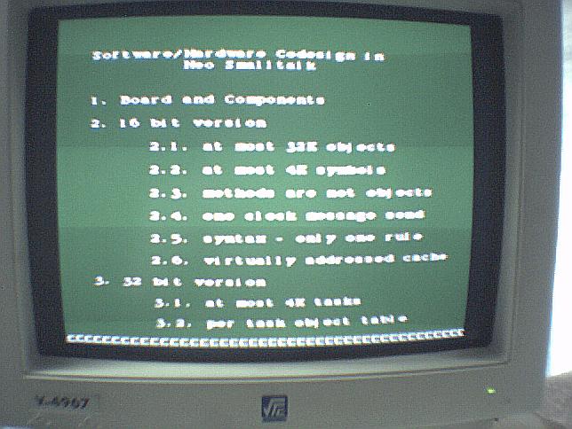
The screen shots would look exactly like those for October 24 (except I added an extra blank line to the "slide" to eliminate the "["s at the bottom) and so won't be repeated here. The difference is that now the machine comes up like that when turned on.
November 13, 2003
Some simple tests confirm that you can't write to the SDRAM while the CPLD is programmed (and probably can't read from it either, though that would be harder to test). So it isn't a Flash-only problem at all.November 12, 2003
All the obvious signals were examined and only the data seem to change when the CPLD is programmed. The "enable" no longer changes like it seemed to do on October 25. The only thing that looks different when the CPLD is programmed is that it keeps generating a waveform at the "CS" pin in the FPGA, but if that is a problem then no circuits should have worked with the CPLD. Changing that to keep the "CS" always inactive during normal operation didn't make any difference.November 11, 2003
The circuit for multiplexing between video and processor generated some ugly glitches and the interface between the memory controller and the external data bus was all messed up, even though it was working. With the most obvious problems fixed, the circuit now works no matter what signals are "copied" to the osciloscope. But only as long as the CPLD is blank.November 10, 2003
A modification so that the signals to the Flash are repeated on the keyboard pins so that they can be seen with the osciloscope makes the circuit not work even when the CPLD is blank.November 5, 2003
The demo circuit no longer works when uploaded from the PC - the screen is all white. But this was just a case of getting the memory map wrong so the font had been uploaded to the wrong place. That was trivial to fix.October 29, 2003
A repeat of the demo/talk of the previous day, but there were only four people as nearly everyone who was interested had seen it the first time. But since the drawings on the flip chart were still there from yesterday, it was possible to go a little faster on the 16 bit part and so get into more details about the 32 bit version. In addition, since this was the last demo of the day we stayed a little while longer having a nice chat.October 28, 2003
Since the prototype was only running Pong, we didn't buy a keyboard for it as originally planned (everyone know what Pong is supposed to be like). Hooking it up to the video projector produced a nice image, but that old demo only has four different colors. After a few seconds the machine was turned off and passed around. Instead of a demo there was a talk using a flip chart to about 80 people.Most of the talk was about the 16 bit design, with a mention about the tasks in the 32 bit version at the very end.
John McIntosh made some pretty detailed notes during the talk, which are include in his OOPSLA03 trip report:
or another by Sean Morris at
October 25, 2003
The demo doesn't work when loaded from the Flash instead of the PC! Everything seems to work but the circuit reads only zeros from the Flash so all characters show up as blanks on the screen. Erasing the CPLD solves the problem, but then there is no way to load from the Flash when the machine is turned on. It is time to leave for the airport, so the Flash was erased and "Pong" was uploaded to it again.October 24, 2003
The Flash upload program in Squeak was modified to also edit and upload fonts. One font was created by copying from the New York 16 bitmap and then making them twice as wide (since most chanracters were less than 8 bits wide and the text mode hardware uses 16 by 16 images). Some characters, like "m", "M", "w" and "W" became truncated in this process and had to be manually patched.To be able to show something interesting, a simple circuit to read from the PS/2 keyboard and write to memory was created. Addresses and data could be typed in hexadecimal (in the normal way, though on the screen they showed up with ":;<=>?" replacing "ABCDEF"). The commands are "\" (set the address to the contents of the buffer), "," (write buffer to memory), "." (read buffer to memory), ";" (show four bits from buffer as hex) and "p" (transfer block of memory, or "print screen"). There were lots of little problems getting the serial ports to work, then the PS/2 keyboard to work and so on. Now it is possible to write to the Flash (but it is horribly awkward to do so) and SDRAM from the keyboard, which allows the machine to be operated without a connection to a PC.
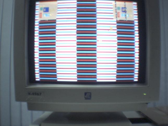
A very poor PowerPoint-like presentation can be made by saving the "slides" at the begining of the Flash memory and then using the "p" command to move them instantly to the screen.
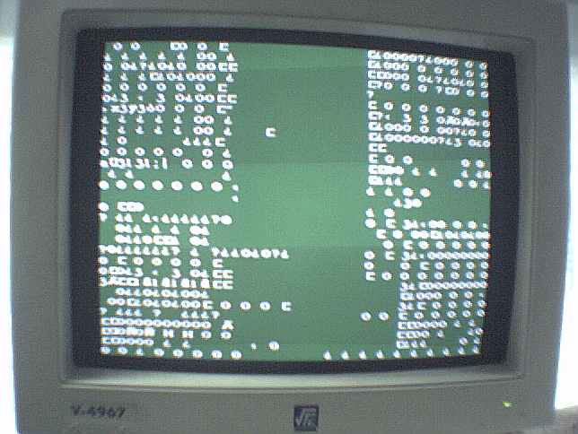
You can also easily get some strange screens - here is the result of copying part of the font bitmaps to the screen memory:
October 23, 2003
A text-mode video output was created by reading pairs of characters from the SDRAM and then the font pattern from Flash. While the processor is mostly complete, there won't be enough time to bootstrap all the needed software.October 22, 2003
Several variations of the drawing demonstrations were developed. Since the memory output goes directly to video there is a lot of flicker due to the variations in timing, specially when there are refresh cycles. In addition, "anti-aliasing" in the zoomed out mode is done by changing the least address bits on every frame. This makes fine details blink and randomizing this sub-sampling didn't help as much as was hoped.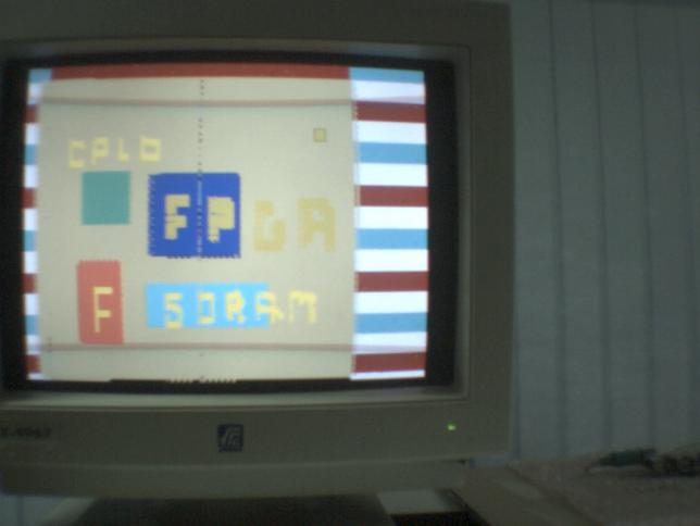
The left mouse button draws with the current cursor, while the right button changes the size and color of the cursor. A better mouse and/or mouse-pad would make it easier to draw reasonable shapes.
The middle button switches between three zoom levels.
The whole screen is 2048x2048 pixels in size, so you have to scroll a lot to see it all in the first zoom level. The second level only shows every 2 pixels, and the third level every 4 pixels (since the screen is over 512 pixels wide we see the left side repeating in this level).
October 21, 2003
Adding 100 ohm resistors to the video outputs corrected the voltage levels. Unfortunately, this patch damaged the adapter board so another one had to be built. (Doh!)October 16 to 19, 2003
The machine was shown at the local high technology fair (except on the 15th, when it was kept in tests to make sure the power supply was now ok).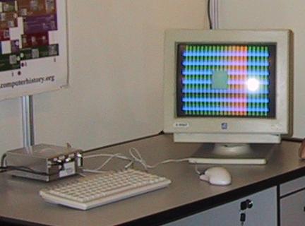
On the last day a half finished drawing demonstration was shown and on the previous days the "Pong" game that had been seen last year was a repeat attraction.
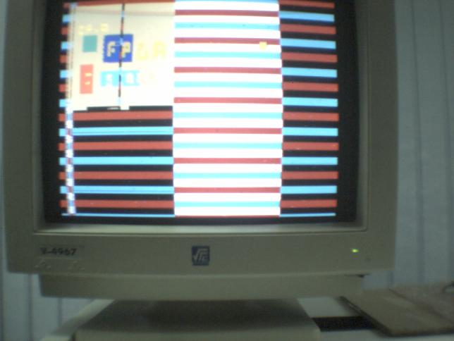
A test with a video projector at another booth showed that the voltage levels were too high (for the TV output needs to go all the way to 1.5V).
October 14, 2003
Here is what the assembled prototype looks like. The computer itself is the green board partly showing on top and the power supply the one partly showing on the bottom.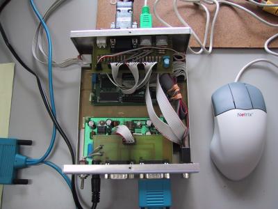
The transistor burned out again and a replacement didn't last long either. So the power supply was redesigned with a LM317T to generate the 3.3V. The cable to the top adaptor board was backwards (since its connector is facing in the opposite direction compared to the lower board) and that was a serious problem, but the mostly likely culprit was the loud speaker which is connected to the 5V and was touching the case, which is grounded. In theory that shouldn't be a problem since the metal parts in the speaker are isolated, but since nobody would be able to hear it in the demos anyway it was simply removed to be on the safe side.
October 13, 2003
The boards for the proto-Merlins (the plan is to make five of them) will not be ready until mid-November, so the one used in the Oliver truck terminal prototype has been borrowed until then for the scheduled demonstrations. The 50Kgate FPGA is enough for one processor and the 512KB Flash and 8MB SDRAM won't be a real limit as the software can't grow very large in just a couple of weeks. The main thing that the larger Flash would buy would be the capability of uploading a few pictures to make the presentations prettier.The transistor for 3.3V in the power supply burned out and had to be replaced.
October 7, 2003
The first proto-Merlin is ready. That includes the two adapter boards, the aluminum case and the labels.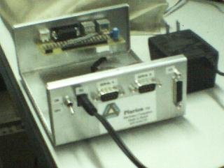
This is the back side of the machine, with the power switch to the left, the DC wall transformer connector, two serial ports and a connector to the FPGA pins so you can attach your own hardware.
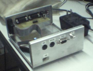
This is the front of the machine, with the two PS/2 connectors on the top left, a SVGA video output, a TV video output and a host USB connector on the bottom.
The dimensions are 15 x 13 x 6 cm (5.9 x 5.1 x 2.4 inches).
September 20, 2003
Layout for the two adapter boards were done using the free version of EagleCAD. Since these machines won't be sold, there is no conflict with the license. In any case, Eagle doesn't handle single sided boards very well so the layout was done manually.September 12, 2003
The main components for six boards arrived. They are the Spartan II 100 FPGAs, 32MB SDRAM, 4MB Flash and CPLDs...Link to this Page
- Desenvolvimento do Oliver last edited on 9 November 2008 at 6:08:02 pm by 192.168.1.23